HEATSINK TECHNOLOGY

VAPOR CHAMBER HEATSINK

You are here:

Vapor chamber cooling is a highly efficient technology in electronic devices and high-performance computing systems. It involves using a sealed chamber filled with a small amount of working fluid, which vaporizes when exposed to heat. This vapor then spreads evenly throughout the chamber, absorbing and dissipating the heat generated by the electronic components. 

Vapor chamber cooling offers several advantages over traditional cooling methods, including better heat transfer, reduced hotspots, and improved overall system performance. It is particularly beneficial in applications where space is limited or where there is a need for high thermal management capabilities.

Vapor Chamber Technology

WHAT IS A VAPOR CHAMBER HEATSINK?

Vapor Chamber Heatsink (VCH) are constructed from sealed copper plates and filled with a small amount of fluid such as de-ionized water that allows heat to be rapidly dispersed away from the source. Inside the chamber resides an internal support structure to prevent the buckling of chamber walls. Classified formally as a heatpipe, a vapor chamber is one of the best heat spreading options at the base of a heatsink; and typically used for high power devices. When combined with stamped fins it creates a high-end thermal management device that can rapidly spread heat from a small source to a large surface area.

Vapor Chamber Technology

A VCH can be integrated with either aluminum or copper heatsinks. The simplest method is to solder a vapor chamber to the base of an extruded heatsink. A more thermally efficient method is to solder a stack of stamped fins directly to the surface of a vapor chamber. To improve the dimensional integrity, these fins are often interconnected by locking tabs called zipper fins.

Vapor Chamber Technology

How a Vapor Chamber works?

A vapor chamber consists of a sealed vacuum vessel, with an internal wicking structure, and a small amount of working fluid that is in equilibrium with its own vapor. The vacuum vessel is typically made of copper, and sealed around the perimeter. The wick can be made of many different substances. The most common way is to sinter copper powder to the inside wall of the vessel. Many fluids can be used as the working fluid of the VCH. But in most CPU, GPU and LED cooling applications, water is selected as the working fluid, because of its high latent heat, high surface tension, high thermal conductivity and suitable boiling temperature, not to mention the cost and environmental concerns.

The low pressure inside the chamber allows the fluid to vaporize at a temperature much lower than its normal boiling temperature. When heat is applied to the VCH, the fluid near that location immediately vaporizes and rushes to fill the entire volume of the chamber (driven by pressure difference). When the vapor comes into contact with a cooler wall surface, it condenses, and releases its latent heat of vaporization. The condensed fluid returns to the heat source by capillary action of the wick structure. As the vaporization and condensation cycle repeats, heat is moved for the heat source to the entire volume of the chamber, resulting in a uniform temperature distribution on its surface. The return of fluid to its boiling location is primarily driven by the capillary force, but gravity and centrifugal force can also contribute to some degree. To utilize the external forces, it is important to design the vapor chamber, such that the gravity or centrifugal force, is working in the direction that drives the fluid from its cold side to the hot side. For example, in a spinning system, the heat source (hot spot) should be located in the outer side of the PCB, and the fins should be located closer to the spinning center.

Two Phase Cooling Solutions

Radian Thermal Products specializes in two-phase cooling technology, known for its superior heat transfer capabilities compared to traditional cooling methods. The process is a combination of liquid and vapor phases that efficiently dissipate heat to maintain optimal operating temperatures.

One of the key advantages of our two-phase cooling solutions is the ability to handle high heat loads without compromising performance. Whether you require cooling for industrial equipment, data centers, or electronic devices, our two-phase cooling solutions can handle the most demanding thermal management requirements.

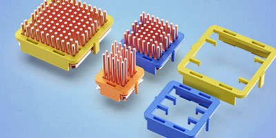
We offer a wide selection of cooling systems, including impingement cooling, direct-to-chip cooling, and cold plate cooling, among others. Our team of engineers works closely with you to understand your specific cooling requirements and recommend the most suitable solution for your application.

What is a Vapor Chamber Thermal System?

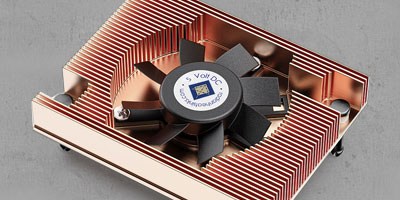
A vapor chamber thermal system is a cooling mechanism that utilizes the principles of phase change to transfer heat away from a heat source. It consists of a sealed copper chamber filled with a small amount of water. The chamber contains a wick structure that helps circulate the working fluid.

The vapor chamber thermal system operates on the principles of evaporation and condensation. When the heat source, such as a high-performance processor or graphics card, generates heat, the water in the chamber absorbs this heat and evaporates. The vapor then moves towards the cooler part of the chamber, where it condenses back into liquid form, releasing the accumulated heat. This cycle continues if there is a temperature difference between the heat source and the cooling fins or heat sink.

Vapor Chamber Benefits

The Benefits of Using a Vapor Chamber

A properly designed chamber combined with a stamped fin heatsink can improve the thermal performance by 10- 30% over copper, and heat pipe based solutions. In mission-critical applications, it not only lowers the temperature by a number of degrees, but also sometimes eliminates the need for a fan on top of the heatsink, which improves the reliability of the system and eliminates noise. It is also perfect for low profile applications where height vs. performance is critical. In addition, a vapor chamber is much lighter than solid copper, due to its internal chamber structure. In many cases, a vapor chamber based heatsink weighs similar to an extruded aluminum heatsink, but works much better than a copper heatsink.

The effective thermal conductivity of vapor chambers is usually 5 to 100 times the conductivity of copper – but it is application specific. The thermal resistance of a VCH comes from many sources. The two major factors are the evaporation resistance and transport resistance. Transport resistance is distance dependent, but it is relatively small compared to the evaporation resistance. Since the dominating evaporation resistance is independent of size, the larger the VCH is compared to the heat source, the greater is the effective thermal conductivity. In a coarse calculation or CFD simulation, it is not uncommon that a uniform and isotropic thermal conductivity, say 10000 W/m-K which is 25 times the thermal conductivity of copper, is assigned to the entire volume of the vapor chamber.

Reliability Testing

Like heat pipes, vapor chambers are very reliable thermal devices. They do not have any moving parts or use any corrosive materials. The working fluid and wick structures are permanently sealed in a copper vessel. There is no mechanical or chemical degradation over time that has been reported by Radian customers. The following tests are routinely performed to confirm the durability and reliability of vapor chambers:

  • Thermal Shock Test
  • Accelerated Life Test
  • Freeze Thaw Test
  • Burst Test
  • Cosmetic Degradation Test

Design Guidelines

The following table shows the suggested operation conditions for typical applications. They are not necessarily the maximum capabilities of vapor chambers.

Vapor Chamber Ambient temperature0 - 85 ºC
Power20 - 700 W
Heat FluxUp to 300 W/cm^2
Size (width and length)50 to 500 mm
Vapor Chamber Thickness2.5 mm and up
Vapor Chamber Flatness0.1 mm in every 25x25 mm area
Vapor Chamber Life (MTBF)100,000+ hours
Through HolesAllowed

Vapor Chamber Heatsink Examples

Vapor Chamber Technology

In this example a copper stamped fins were attached to a vapor chamber to create a very high performance heatsink. Two zipper fins were used to create a solid structure, and a cut out was created to allow for the push pin location.

Vapor Chamber with Light Engine

In this example, a light engine was mounted onto a custom vapor chamber.

Standard Vapor Chamber Heatsink

Standard Vapor Chamber Heatsinks

Radian has introduced a line of standard VCH. A properly designed VCH combined with a stamped fin heatsink can improve the thermal performance by 10- 30%, but because of the complexity of the chambers, and other factors such as source size and chip height, the thermal performance of a VCH must be evaluated through thermal simulation or actual testing. Most are available for shipping within a few days.

In many cases, the weight is similar to an extruded aluminum heatsink of the same performance rating. If the standard options do not fit your requirements, they can be modified using a standard base. If the existing hole patterns do not work, a completely new vapor chamber can be designed and manufactured.

Vapor Chamber Specifications

PartDescriptionMaterialFinishWidth (mm)Length (mm)Height (mm)Power Rating (W)Theta SA (°C/W) at 200LFMTheta SA (°C/W) at 400LFMTheta SA (°C/W) at 600LFM
VCH1044Vapor Chamber HeatsinkCopper/ Copper FinsNickel Plated93112161500.980.520.38
VCH1101Vapor Chamber HeatsinkCopper/ Copper FinsNickel Plated719421.51500.580.320.24
VCH1102Vapor Chamber HeatsinkCopper/ Copper FinsNickel Plated719421.51500.60.350.27
VCH2158Vapor Chamber HeatsinkCopper/Aluminum FinsNickel Plated117908.331500.850.520.42
VCH2185Vapor Chamber HeatsinkCopper/ Copper FinsAnti-Oxidation1179027.61500.280.150.11

Copper or Aluminum

Custom designs

Rapid Prototyping

Steam away the heat!